Monday 2 December 2019

The Last Emily : Kanoya's Nishikawa H8K2 Type 2 Flying Boat


The Kawanishi H8K2 Model 12 Type 2 Flying Boat
Allied code name Emily at Kanoya Air Base Museum.
Source Wikipedia


Most of us are familiar with combat aircrafts of World War II like the North American P-51 Mustang, the Supermarine Spitfire, the Messerschmitt Me-109, the Boeing B-29 Superfortress, the Avro Lancaster and maybe even the Consolidated PBY Catalina. But how about the Kawanishi H8K? I must confess I did not know of its existence until my recent visit to the naval aviation museum of Kanoya Air Base in Kagoshima, Japan.


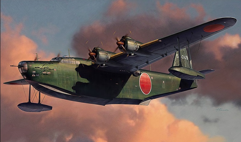
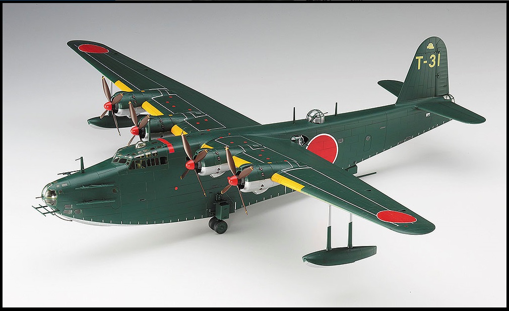
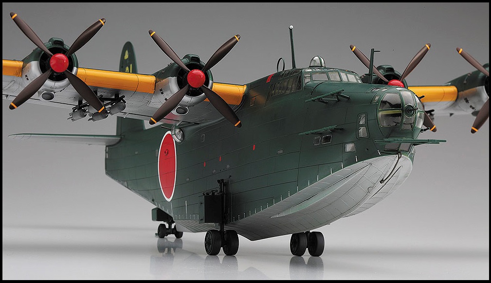
The Kawanishi H8K2 Emily Type 2 Flying Boat. Source : Hasegawa Model Co.


Kawanishi H8K


The Kawanishi H8K was a large 4-engine maritime aircraft used by the Imperial Japanese Navy Air Service ( IJNAS ) during WWII. It was commonly known as the Nishiki Hikotei ( 二式飛行艇 ) or Type 2 Flying Boat and its allied reporting name was " Emily ".

It was manufactured by the Kawanishi Aircraft Company ( 川西航空機 ) which was well known for its various seaplanes. Its chief designer was Kikuhara Shizuo ( 菊原静男 ).

The H8K was fast, has a large lifting capacity and very long range. It was robustly built and also has a very comprehensive set of defensive armaments. It saw service between 1941 to 1945 and was deployed in maritime patrol, bombing, reconnaisence and transport missions. Many including the aviation author René Francillon considered it to be one of the most outstanding maritime combat aircraft of WWII. A total of 167 H8K of different variants were built during the War but as of today only one has survivied and it is now displayed at the Kanoya Air Base Museum ( 鹿屋航空基地史料館 ).


Kawanishi H8K2 Model 12 Emily at Kanoya Air Base Museum. Source : Wikipedia


Emily of Kanoya 


The Kanoya Air Base Museum is one of three museums managed by the Japan Maritime Self Defense Force ( JMSDF ) and is dedicated to the history of naval aviation. Kanoya Air Base itself was a major IJN airfield during WWII and was extensively involved with conducting Kamikaze suicide attacks during the closing years of the War. Today it is the headquarters of JMSDF's Fleet Air Wing 1 with its P-3C Orion anti-submarine unit, search and rescue unit and 2 helicopter training units.

The museum has a large collection of legacy Cold War era naval aircrafts and helicopters previously in service with the JMSDF but also a restored Mitsubishi A6M5 Model 52c Zero fighter and as mentioned the H8K Type 2 flying boat.

There is no doubt whatsoever that the crown jewel of Kanoya has to be the one and only Kawanishi H8K left in the world so much so that the museum has made the flying boat the official museum mascot and has created a caricature in the form of a flying whale called Nishiki Don.


Nishiki Don : the whale mascot of Kanoya Air Base Museum


But how did this Emily, a H8K2 Model 12, end up at Kanoya? I discovered that there was a convoluted story behind the preservation of this Type 2 flying boat. One that began with long trip across the Pacific to the United States, an extended period of storage, a subsequent reunion with its designer and a long drawn campaign to bring it back to Japan.


Some significant land marks in the history of the last Emily.


Survivor


It was said that when Japan surrendered on 15th Aug 1945, there were only four surviving Kawanishi H8Ks in all of Japan. Three of them were air worthy and they were located at the Nanao Auxillary Seaplane Station in Ishikawa Prefecture. However, one crashed and sunk off the coast of Shimane in transit to Takuma Naval Air Station located in Kagawa Prefecture within the Seto Inland Sea. Takuma was then one of the major seaplane base hosting the Type 2 flying boats.


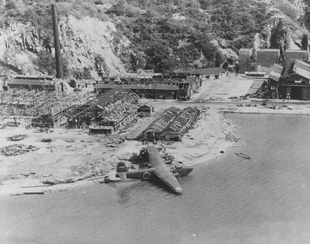
Kawanishi H8K2 Emily Flying Boat beached at a
damaged installation in Japan circa late summer 1945.
Source : Naval History and Heritage Command


By 22nd Aug 1945, all three surviving H8Ks were at Takuma. An unverified source mentioned the US commander only wanted to keep one aircraft for tests and evaluation so the other two were eventually destroyed. To maintain the H8K in flyable condition was a tall order as demobilization was on ongoing and the was just not enough manpower for the up keep of the huge plane. Somehow a seven man team of technicians was recruited from the Kure Naval Arsenal and they had the H8K fixed by October 1945. With a team of six flight crew, Lieutenant-Commander Hitsuji Tsuneo ( 日辻常雄 ) who was then commander Takuma Naval Air Group, successfully flight tested the Type 2 flying boat without any incidents. On 13th November 1945 Hitsuji and his team flew the H8K to Yokohama, tailed by a PBY Catalina. He noted that the journey took him about one and a half hours while the slower Catalina took slightly more than two hours. From Yokohama it was ferried to Naval Air Station ( NAS ) Whidbey Island, Washington, where she was found to be not air worthy. The Emily was then shipped via the Panama Canal to NAS Norfolk where the Overhaul and Repair Facility had the herculean task of overhauling and reassembling the aircraft without the benefit of blueprints, technical manuals and spare parts, starting December 1945.

The Emily had thus far accumulated 15000 flight hours and upon the completion of her refurbishment, she was flight tested on 23rd May 1946 during which she was flown from Hampton Roads to NAS Patuxent River less than 100 miles away. Two engines had malfunctioned during the flight while a third stalled shortly after landing but none of the American aviators were injured. It seemed the Emily would never fly again. At NAS Patuxent River, hydrodynamics tests began on 22nd Aug 1946. By 30th Jan 1947, the test and evaluation program was terminated. The aircraft was taken apart, wrapped up in protective coating, crated up and shipped back to NAS Norfolk where she was mothballed under the responsibility of the Naval Air Rework Facility.

The Hampton Roads Naval Museum blog has an excellent collection photographs and information of the Emily while in the custody of the Americans.

The Japanese Internet Aviation Magazine Contrail ( Hikoki Gumo ) 航空雑誌ヒコーキ雲 has large collection of photographs and information of the Emily after her return to Japan.


Hitsuji Tsuneo wrote the book
The Last Flying Boat ( 最後の飛行艇 )
published by Kojinsha ( 光人社 )


Post War Restructuring


Meanwhile aircraft manufacturing was completely banned beginning from December 1945 during the Allied Occupation and the Nishikawa Aircraft Company tried to transform its business model to cater to a completely different peacetime market. By 1946 it was churning out daily commodities to help alleviate shortages in goods and food. It also made motorcycles and three wheeled light trucks. It was renamed Meiwa Industries in July 1947. In 1949, in compliance with some corporate restructuring law, the company was split and renamed Shin Meiwa Industry Company. Its automotive arm Meiwa Automotive Industries was divested to a certain car company known as Hatsudori Seizo Co, which in 1951 would be renamed Daihatsu Motor Co.

Rid of the automotive arm and retaining its core aircraft manufacturing and overhaul business, Shin Meiwa  ( which means New Meiwa ) soldiered on with heavy machinery and aircraft component manufacturing and eventually saw a change of fortune with the end of the Allied Occupation and the lifting of the aircraft manufacturing ban in 1952. In 1953 it had started to research on a new generation of amphibious aircraft with greater sea-worthiness based on an initial idea by Kikuhara Shizuo, the chief designer of the H8K. By 1957 the research team had successfully overcome two technological hurdles by inventing a wave suppressor and a high lift device which allowed for low take-off and landing speeds, thus paving the way to developing a short take-off and landing seaplane.

However, Shin Meiwa would soon face a new challenge in securing the necessary funds to develop the amphibious plane and the company started pitching the seaplane as the most effective means of anti-submarine patrolling with the hope that the Japanese government would start placing orders. Its PR efforts eventually drew the attention of the US Navy who would then invite Kikuhara to Washington D.C. in 1959.


Reunion and Failed Repatriation  


During his one month tour of the United States, Kikuhara Shizuo had the opportunity to visit many American research facilities including those at NASA. He observed experiments conducted in large scale water troughs and various wind tunnels and spoke with researchers over technical issues. He had also met with high ranking US naval officers and managed to obtain the promise of total support in terms of technology and materials so long as the JMSDF would make an official request. He promptly asked to be given one the US Navy's seaplanes so that he could test the new technology on an experimental plane before further development. His request was eventually accepted and a Grumman HU-16 Albatross was given to the Japanese who reverse engineered and reassembled it to build the UF-XS testbed seaplane. Shin Meiwa would then go on to produce the PS-1 anti-submarine patrol plane and later its SAR variant the US-1.

Kikuhara also toured NAS Norfolk during his working trip to Washington D.C. where he found the mothballed Emily placed in the open. In an article he later wrote for the Japanese magazine Koukuu Jyouhou ( 航空情報 ) or Aviation News, he described the plane as being preserved in fairly good condition. It was wrapped in a special rubber coating like a cocoon and the entrances were sealed. Some kind of air conditioner blew dry air into the interior of the fuselage and kept the humidity level at 28% on the day of the visit and generally less than 30% during the more than 10 years of preservation. He negotiated for its return but was unsuccessful this time as the US had decided on its permanent preservation on American soil.

A year after Kikuhara's visit, in September 1960, the Emily would suffered extensive damage when Hurricane Donna struck and ripped it off its moorings and tipped it over to its starboard side breaking loose engine number 4. Donna was the strongest Atlantic hurricane of 1960 and the strongest to hit the eastern seaboard since 1935.


Photo of Kikuhara Shizuo in an article he wrote in
Koukuu Jyouhou ( Aviation News ) magazine on his American trip
Source Internet Avaition Magazine Hikoki Gumo ( 航空雑誌ヒコーキ雲 )


The H8K2 Emily at the Tokyo Maritime Science Museum


Return To Japan


In the following years, the campaign for the return of the H8K to Japan continued, lead by a prominent psychiatrist Dr Saito Shigeta ( 斎藤茂太 ) ( 1917 - 2006 ) who was also an aviation enthusiast and an essayist. The movement eventually bore fruit in 1978 when the Americans decided to do away with the aircraft due to cost cutting constrains. Of the various organizations and individuals that offered to get the Emily off the hands of the USN, the Tokyo Museum of Maritime Science ( 船の科学館 fune no kagakukan ) was selected as it fulfilled the transfer criteria : it was a non-profit organization and it had the funds for the relocation. The transfer was subsequently approved by Congress and a ceremony was held on 23rd Apr 1979 to mark the event. The Emily departed Norfolk on 31st May 1979 and was put on a cargo ship the New Jersey which arrived at the Oi Container Terminal in Tokyo on 13th July. One week later, the H8K was transferred to the Tokyo Museum of Maritime Science and Lt-Commander Hitsuji was in attendance at the receiving ceremony. Restoration works commenced on 20th Feb 1980. The restored H8K was unveiled to the public on 27th March 1982, becoming part of the outdoor exhibit of the Maritime Science Museum until 2004 when it was finally relocated to Kanoya Air Base Museum.


Dr Saito Shigeta was instrumental in
the eventual return of the H8K to Japan

The reasons for the transfer to Kanoya was not apparent to me but it may have something to do with the death of the Museum of Maritime Science's founding president Sasakawa Ryouichi ( 笹川良一 ) in 1995 and perhaps to the lack of funding from his Sasakawa Foundation ( later Nippon Foundation ) thereafter. The museum has been effectively closed since 2011 with only a few ships still open to the public at its annex location. Sasakawa was a shady and controversial Japanese businessman with connections with the political elites and the underworld. He was once imprisoned as a class A war criminal from 1945 to 1948 but was subsequently released without facing charges. He made his fortunes supplying the Imperial Japanese Army in Manchuria from 1932 and post war through monopoly of the betting activities on motor boat racing, among other things.


The Emily displayed at the Maritime Science Museum whose main building
takes the shape of a ship. This old image was dated Dec 1997 


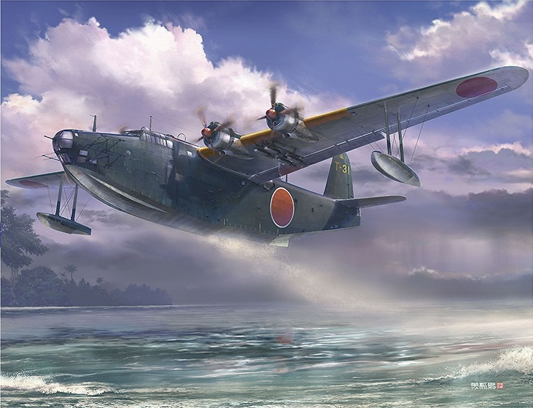
The H8K2 Model 12 taking-off. Source : Hasegawa Model Co.


Aircraft Specifications H8K2 Model 12


Length  :  28.13m
Width   :  38.00m
Height  :  9.15m
Wing Area : 160m²
Empty Weight  :  18400kg
Gross Weight    :  24500kg
Maximum Weight : 32500kg
Powerplant : 4 x Mitsubishi Kasei MK4Q Model 22  14 cylinder air-cooled radial piston each 1850hp
Max Speed : 453 km/h at 5000m altitude
Range : 7200km
Armament : 5 x 20mm Type 99 cannon
                    4 x 7.7mm Type 92 machine guns with another 3 in reserve
                    2 x 800kg torpedoes or
                    2000kg of bombs and depth charges
Radar         : Mark VI Model 1 ASV radar.
Compliment : 10                    
Take-off Distance 295m


The photographs below from Hasegawa Model Co show the completed 1:72 scale model of the Nishikawa H8K2 Model 12 with decals exactly as the last Emily at Kanoya. The tail code T indicates this aircraft operated out of Takuma Naval Air Station. Earlier during the War the IJNAS used the hiragana たく ( taku ) instead on aircrafts from Takuma.


Seaplane Tender Akitsushima


When writing about the H8K, it is impossible to omit the mention of the seaplane tender that maintain, resupply and repair the Type 2 flying boat in theatre. The IJNS Akitsushima ( 秋津洲 ) was a seaplane tender specifically built to handle the large seaplanes of the IJN. Its most unique feature was the 35 ton crane near the stern that was capable of lifting the 31 ton H8K. The 5000 ton ship can carry 689 tons of aviation fuel, 36 torpedoes and almost 62 tons of bombs ( 100 x 60kg, 100 x 250kg, 15 x 500kg, 30 x 800kg ). It can accommodate the H8K on its deck but only when in anchorage since the wingspan of 38m was much greater than the beam of the ship at 15.8m. It was just not possible with the rolling motion when the ship was underway.


IJNS Akitsushima with its fancy camouflage. Source Wikipaedia

 
IJNS Akitsushima with its fancy camouflage 1:700 scale. Source : Aoshima Model Co


IJNS Akitsushima with H8K on deck. Source Aoshima Model Co.

Erroneous depiction : Akitsushima underway with Emily onboard!
Not possible! Source : Aoshima Model Co 


Preserving Emily


As usual, in the immediate aftermath of many conflicts, the last thing in the minds of either the victor or the vanquished would be to save some war relic for future historical and heritage purposes. There were just too many other urgent and pressing issues to settle, like the demobilization and repatriation of veterans and the resettlement of refugees, food shortages, re-establishing the healthcare system, nation rebuilding etc.

The Kawanishi H8K was a brilliant piece of aero-nautical engineering representing the best of Japanese wartime aircraft design and manufacturing capabilities. It was unfortunate that only one would survived the War and would be taken away from Japan, rightfully by the Americans as the victors.

To the credit of the Americans, they did not simply discard or scrap the H8K after toying with it but instead mothballed it. Since they were short on funds, the USN could have donated the Emily to the National Air Museum ( subsequently renamed Smithsonian Air and Space Museum ) whom I am sure would be very glad to have her, especially knowing that this was the last H8K in the world. However, should that have happened, the Emily would become just another aircraft among the thousands of equally rare and precious aircrafts in the Smithsonian collection.

It would have been more meaningful for the Emily to be returned to Japan, to be treasured and to be seen by the generations of Japanese who has never experienced the horrors of war. Fortunately the perseverance of Saito Shigeta and his follow countrymen eventually saw the Emily being returned her country of origin. I cannot imagine what would have gone through the mind of chief designer Kikuhara Shizuo when he found his Emily languishing in Norfolk and the anguish of not being able to successfully negotiate for her return. It was after all his creation. After 33 years of solitude in America, it was like a fairy tale ending that the Emily was received by her last Japanese pilot commander Hitsuji Tsuneo on her return to Japan.

The Emily has out-lived her designers, builders and the airmen and technicians that maintained and flew her. At Kanoya, she will continue to inspire future generations of aeronautical engineers, airmen and educate, Japanese and foreign visitors alike, about Japan's dark wartime history.


Foot Note


A flying boat is a fixed-wing seaplane with a hull that allows landing on water. Its purpose-designed fuselage gives the aircraft buoyancy and allows it to float on the water surface. It usually does not have any sort of landing gear to allow operations on land. The wheels on the H8K, known as beaching wheels, are not designed to withstand the impact of landing on an airstrip.

A floatplane in contrast uses floats beneath the fuselage to provide buoyancy. The fuselage is lifted above the water surface by struts and supports.

An amphibious plane is a seaplane, either flying boat or floatplane, that is also fitted with landing gear that allow for take-off and landing on land


Shin Meiwa Industries has been rebranded ShinMaywa Industries since 1992 in an attempt to make the company name more pronounceable for foreigners. It currently produces the US-2 SAR amphibian, an evolved version of the US-1.


Thursday 27 June 2019

Gone In 35 Seconds : Spatial Disorientation And The First Fatal F-35 Crash  


 F-35A Photo : JASDF


The Lockheed Martin F-35 Lightning II is one of the newest and most advanced tactical fighter that is beginning to populate the air forces of the United States and some of its allies in sufficient numbers to make a difference operationally. Despite having a difficult development cycle which was plagued with everything from cost over-runs to performance issues, the F-35 has a relatively benign safety record and managed to remain crash-free for 12 years since its first flight. That all changed in October 2018 when a US Marine Crops F-35B suffered engine failure and crashed during a routine training flight in South Carolina. Fortunately there were no fatalities as the pilot managed to eject safely.

The first and only fatal crash of the F-35 occurred on 9th April 2019 and it involved a Japan Air Self Defense Force F-35A operating out of Misawa Air Base ( 三沢基地 ). The crash site was the Pacific Ocean some 135km due east of Misawa. The pilot apparently flew the aircraft at high speed into the sea and did not send any signal of distress nor attempted to eject prior to impact. Parts of the wreckage were found scattered over a wide area on the seabed at a depth of 1500m. After 2 months of investigations, the JASDF concluded that spatial disorientation was most likely the cause of the mishap though gravity induced loss of consciousness could also be a remote possibility.

How could an accident like this happen and what is spatial disorientation? Could better pilot training have prevented such an accident?


F-35A 89-8706 Photo : JASDF


Japan's F-35A


The Japanese MOD placed an initial order for 42 F-35A back in Dec 2011 to replace its fleet of ageing F-4EJ Phantoms. 4 would be assembled at Lockheed Martin's Fort Worth plant while the rest would be built at the Mitsubishi Heavy Industries Komaki South F-35 Final Assembly and Check Out ( FACO ) facility in Aichi Prefecture. In those days the unit cost of the F-35A was USD126million or about JPY14billion. JASDF has so far received 13 F-35A and they are assigned to the 302nd Tactical Fighter Squadron of the 3rd Air Wing based at Misawa Air Base. Misawa is located in Aomori Prefecture in the North-eastern region of Japan. Aomori is famous for its apples and also for its scallops farmed in Mutsu Bay.


F-35A 79-8705 at Misawa AB on 2 Nov 2017 for safety checks
 before its trans-Pacific flight to the US. USAF Photo
 
 
JASDF F-35A 79-8705 escorted by a USAF F-16 assigned to the 115th Fighter Wing,
Wisconsin Air National Guard on its maiden voyage across the Pacific on 6 Nov 2017.
Photo : USAF


The Fatal Accident


According to press release information from JASDF ( Japanese only ), the F-35A that crashed had the serial number 79-8705 and production number AX-5. It was the first Japanese-assembled F-35A and it was only unveiled at the Komaki plant on 5th Jun 2017. Its first flight was on 12th Jul 2017. It was flown to Misawa AB on 2 Nov 2017 to prepare for the trans-Pacific flight to the US for final flight testing. This was to ensure all future Japanese assembled F-35s were up to standard. It went into active service on 28th May 2018 with the transitional F-35 squadron, a temporary unit of the JASDF, before the aircrafts were assigned to the 302nd TFS. The 302nd TFS had been operating out of Hyakuri AB for several years and only completed the relocation to Misawa Air Base in March 2019.

The pilot was subsequently revealed as Major Hosomi Akinori ( 細見彰里 ), a 41 year old veteran with 3200 hours of flight experience but only 60 of those hours were type specific for the F-35A. Japanese media stated that this aircraft has the latest Block 3F mission software with full warfighting capability.


F-35A 79-8705 at Nagoya Airport NKM/RJNA on 2 Nov 2017
Photo Yabyansan via flyteam.jp


On that fateful Tuesday evening of 9th April 2019, the sun had set at 1805 hours. Maj Hosomi was the flight leader for a group of four F-35A on routine air combat maneuvering ( ACM ) training over the Pacific Ocean off the coast of Aomori. The formation took off from Misawa Air Base at 1859 hours and proceeded to perform two-on-two ACM training. At 1925 hours Maj Hosomi reported that the two opposing aircrafts had been shot down in the training with the transmission " 21, two kills ", 21 being his call sign. At 1926 hours the F-35A was at an altitude of 31500ft when ground controllers advised the major to make a turn to port and to descend in order to maintain a safe distance from an approaching US military aircraft ( type unspecified ) at 37000ft. Maj Hosomi replied " Affirmative, Roger " and began his turn and descend. Twenty seconds later, upon completing the turn and by then descended to 15500ft, Maj Hosomi transmitted in a calm voice " Roger, Knock it off " ( meaning termination of training ). Information from datalink and ground radar would later reveal that at this stage the F-35A descended with a speed of 900km/h. Within the next 15 seconds, the F-35A would continue its rapid descend from 14500ft with a speed of 1100km/h and then disappeared from the radar screens when it plunged below 1000ft. The time of impact was estimated at 1926 hours 30 seconds.


Plan view ( view from above ).
Red arrow shows path of Hosomi's F-35A.
Green arrow shows passing US military aircraft.
1. 1925hrs  2. 1926hrs  3. 1926hr15s  4. 1926hr30s
Source : JASDF


Side View ( vertical view ) Source JASDF


Spatial representation of F-35A final flight path. JASDF


Search and Rescue


The search and rescue ( SAR ) effort was probably activated the moment team mates and ground control lost contact with the distressed F-35A. JASDF reported that by 1947 hours eleven of their SAR assets were already airborne. At 1950 hours 5 ships and 2 aircrafts from the Maritime Self Defense Force ( JMSDF ) also joined the search effort. At 2145 hours floating debris had been located. Some of these were later recovered by a UH-60J helicopter from the SAR team operating out of Akita at 2210 hours. At 2248 hours the destroyer escort Chikuma was also on site to recover floating debris. The Air Staff had by then ( 2230 hours ) established an accident investigation committee. Eventually US Forces Japan and the Japanese Coast Guard would also chip in with SAR assets. The various units involved in the immediate SAR effort were as follows:

JASDF : 2 x U-125A and 2 x UH-60J Blackhawk
JMSDF : 1 x P-3C Orion and 1 x SH-60J Seahawk and 5 ships
USFJ    : 1 x P-8 Poseidon
JCG      : 3 ships


U-125A SAR Bizjet


UH-60J SAR Helo


Crash site is in the Pacific Ocean 135km east of Misawa AB.
Exact location of the wreckage is kept secret for obvious reasons.


Recovery and Salvage


In the week following the crash up to 17th April, multiple P-8A Poseidon Multi-mission Maritime Aircraft and the guided missile destroyer USS Stethem ( DDG-63 ) also joined in the JASDF-led search effort covering some 5000 sq nautical miles in area.

The USN subsequently chartered a commercial dive support and construction vessel, the Van Gogh, to assist in the search. The Singapore-operated Van Gogh with its onboard USN salvage team supported the search efforts of the research vessel Kaimei, owned by the Japan Agency for Marine-Earth Science and Technology ( JAMSTEC ) and the JDS Chiyoda, a submarine rescue tender of the JMSDF. The 5747t Kaimei has sophisticated equipment to conduct high resolution 2D and 3D survey of the seafloor and is equipped with a remotely operated vehicle that can dive to a depth of 3000m.

The USN also deployed the latest version of its cable-controlled undersea recovery vehicle, the CURV-21 and the TPL-25 ( Towed Pinger Locator ) system in the salvage operation. On or after 3rd May, parts of the flight data recorder a.k.a. the black box were recovered. It was however severely damaged and no useful data could be retrieved. Its recovery therefore did not help in the crash investigation. Much of the wreckage were scattered in a wide area under 1500m of seawater.


The Kaimei deep-sea research vessel

The Van Gogh transiting Naha, Okinawa on 16th April 2019.
Credit on photo.
 
TPL-25 is a towed sensor used for locating emergency relocation pingers
 on downed navy and commercial aircraft at a maximum depth of 20000ft.
USN Photo 


The USN finally called off the search and salvage effort on 8th May though the Japanese MOD felt obliged to continue until they too gave up on 4th June, almost 2 months after the crash. Maj Hosomi's body was never found and his death was confirmed by the Japanese MOD on 7th June. Following the crash Japan has grounded its remaining fleet of 12 F-35A and suspended pre-delivery flight tests for the 14th F-35 from MHI's Komaki FACO facility.


Air Crash Investigation


With the paucity of information obtainable from the wreckage, the crash investigators had relied heavily on communications, ground radar tracking and peer-to-peer datalink information from the F-35's Multifunction Advanced Data Link ( MADL ) to reconstruct the unfolding events prior to the fatal accident. They eventually came to the conclusion that it was most likely due to pilot error, specifically spatial disorientation, that caused the crash. Engine failure was possibly ruled out as the aircraft in question was flying quite normally less than a minute before the crash and there were no signs that the pilot found anything amiss and no alarm had been raised regarding any malfunctions. The last radio transmission from the pilot in a calm voice 15 seconds prior to impact also supported the fact that nothing of distress had been detected at that point in time.

The investigators also somehow determined that Maj Hosomi did not attempt to eject from his aircraft as it was barreling towards the surface of the sea and neither did he respond to alerts from the aircraft's warning systems such as the ground proximity warning system.

The execution of several abrupt maneuvers in rapid succession which included turning, rolling and descending could have severely affected his spatial awareness leading to the wrong corrective actions, potential converting a dangerous situation into an irrecoverable one. The final verdict of the investigators named spatial disorientation to be the most likely cause of the fatal crash with gravity -induced loss of consciousness as a remote possibility.

So what is spatial disorientation and what role does it have in aviation disasters? In order to understand spatial disorientation, we need to dwell into realm of aeromedical physiology a little.


Introduction to Spatial Disorientation by Hank Caruso
Image : Naval Aviation News


Spatial Orientation


Spatial orientation refers to the natural human ability to maintain our body orientation and posture in relation to our physical environment, at rest and during motion. From an evolutionary point of view humans are adapted to maintaining spatial orientation to the ground. Three-dimensional environments encountered during flight or deep diving are unfamiliar to the human body and can create sensory conflicts and illusions that makes spatial orientation difficult or sometimes impossible to achieve.

According to the Federal Aviation Administration ( FAA ), statistics show that between 5 to 10% of all general aviation accidents can be attributed to special disorientation, of which 90% are fatal.


Sensory Systems


Achieving spatial orientation requires the effective perception and interpretation of sensory inputs from the visual, vestibular, proprioceptive and auditory senses.

Visual references provide the dominant sensory information to maintain spatial orientation. This is especially true if our body and / or environment is in motion.

The vestibular system located in the inner ear has two distinct components with the 3 semicircular canals responsible for detecting angular acceleration ( rotational movements ) in 3 different axis corresponding to the pitch, yaw and roll movements of an aircraft while the otolith organs ( utricule and the saccule ) detects linear and gravitational acceleration respectively.

The proprioceptors are sensory receptors located in the muscles, tendons, joints and skin that play a small role in maintaining spatial orientation. They do however give some indication of posture by sensing the relative position of our body parts in relation to each other and by sensing points of physical contact between body parts and the surrounding environment.

Auditory input has the smallest role among all the senses involved in maintaining spatial orientation.

The Federal Aviation Administration videos below may help you understand the functions of the vestibular system.


Vestibular Illusions Leading To Disorientation


Since visual cues are the most important sensory input for maintaining spatial orientation, the loss of a reliable external visual reference point such as the horizon at night or in adverse weather may lead to the vestibular and proprioceptive systems not interpreting the actual motion of the body through space correctly. Here are some of the vestibular illusions that can occur during flight. Somatogyral illusions originate from the semi-circular canals while somatogravic ones originate from the otolith organs :

The Leans ( somatogyral ) - sudden return to level flight after a gradual and prolonged turn that was unnoticed by the pilot

The Graveyard Spin ( somatogyral ) - entering a prolonged ( more than 15 or 20 seconds ) spin intentionally or unintentionally, the pilot gradually loses the sensation of turning and when the turn is corrected feels a strong sensation of turning in the opposite direction. Any attempts to correct this false illusion results in the aircraft returning to spinning in the original direction, all the while losing altitude. Ground impact is inevitable unless this spatial disorientation is recognized early.


The Graveyard Spiral ( somatogyral ) - similar to Graveyard spiral but caused by return to level flight after prolonged intentional or unintentional bank turn.

The Coriolis Illusion ( somatogyral ) - also known as the cross-coupled stimulation, it is a severe tumbling sensation brought about by moving the head out of the plane of rotation, simultaneously stimulating one set of semi-circular canals while deactivating another set. It can happen when the pilots tilts his head upwards, downwards or sideways when the aircraft is turning. It causes a strong and unpleasant sensation of tumbling which often has a rapid onset. The tumbling feeling can be bad enough to cause nausea and the pilot may feel the aircraft pitching, rolling and yawing all at the same time. It can result in the pilot quickly becoming incapacitated by vertigo and losing control of the aircraft. The severity of this phenomenon is a function of the magnitude of the initial turn, the direction of the head movement and the speed at which the head movement is made.

The G-Excess Illusion ( somatogyral ) - a vestibular illusion that can occur even in VFR ( visual flight rules ) conditions. Happens when the aircraft enters a tight turn that puts more than 1G load on it and the pilot looks back at the turn. An illusion of underbank occurs if the head is facing the inside of the turn elevated or if the head is facing the outside of the turn depressed. The pilot can erroneously perceive that the angle of bank and G-load are decreasing. The instinctive reaction to apply more bank could stall the aircraft or result in ground impact and is particularly dangerous in low altitude and high speed operations. Here's a USAF video on the G-Excess illusion.


Inversion Illusion ( somatogravic ) - usually involves high performance aircrafts, a steep ascend followed by a sudden return to level flight causes the illusion of tumbling backwards or being inverted. The pilot invariably respond by lowering the nose of the aircraft which intensifies the illusion.

Head-Up Illusion ( somatogravic ) - sudden forward linear acceleration during level flight creates illusion that the nose of the aircraft is pitching up. The pilot's response is to pitch the nose down. Night take-off from a well-lit airport into a completely dark sky and carrier catapult take-off are examples that can cause this illusion.

Head-Down Illusion ( somatogravic ) - sudden linear deceleration during level flight creates sensation that the aircraft is pitching down. The pilot may then pitch the nose up and if this occurs when the airspeed is already low such as during final approach, a stall may be inevitable.

With so many possible scenarios that can lead to spatial disorientation, I have had a new found respect for aviators, especially those who fly advanced military fighter jets. It should be noted that visual illusions, of which there are just as many compared with vestibular illusions, have yet to be included in the discussion since they are not relevant in the final flight of F-35A 79-8705.


G-Excess Illusion by Hank Caruso
Image : Naval Aviation News


What Could Have Happened


The sky would be dark over the Pacific Ocean off the coast of Misawa by 1926 hours on 9th April 2019. The waxing crescent moon would have been setting and close to the south-western horizon. The ocean surface would have been dark save for a few dim lights from fishing vessels or the occasional commercial vessel transiting through that area. If there were significant cloud cover on that night, it could have made things worse. Therefore one could possibly conclude that there would have been little visual input for Maj Hosomi and his team when they were flying that night. The most important sensory system for maintaining spatial orientation had been removed.

If the flight path diagrams released by the MOD were drawn to scale and were accurate, we can see that Maj Hosomi's F-35 did make some maneuvers in its final 2 minutes of flight that could potentially trigger spatial disorientation. There was the sustained turning which began from 1925 hours when he was directed to descend but at no point was there a sudden return to level flight. There was also an initial rapid descend followed by an even more acute turning rate before the final plunge.

From the communications intercepts, Maj Hosomi was still communicating normally 15 seconds prior to impact. So it is likely that the spatial disorientation could have taken place earlier but went unrecognized by Maj Hosomi or a sudden and highly debilitating event could have taken in the last 15 seconds of flight.

Looking at the flight profile I would say a G-Excess type spatial disorientation could be the most likely illusion encountered by Maj Hosomi. After all, he was turning at relatively low altitudes ( 14500ft and below ) and at very high speed ( in excess of 1100km/h ) in the final 15 seconds of flight. Looking back at the turn at this point in time could trigger the G-Excess phenomenon and if he had responded inappropriately by increasing the angle of bank without a corresponding increase in back pressure on the stick, the result will be a rapid deterioration into a controlled flight into terrain ( CFIT ) situation. There may simply not be enough altitude or time for recovery.

The Coriolis type phenomenon is also possible during the final turn taken by the F-35 as Maj Hosomi could have inadvertently looked up, down or sideways during the turn thus triggering the incapacitating tumbling sensation characteristic of this vestibular illusion. It could be severe enough to make him lose control of the aircraft.

Contributing factors that could have lead to the loss of spatial orientation include fatigue, inclement weather, unexpected change of flight plans, distractions caused by equipment malfunctions, personal time pressures and even the personal attitude of the pilot ( self-confidence ). Many of these factors could be at work on that fateful night.


The waxing crescent moon on 9th April 2019


The waxing crescent moon would be close to the southern horizon
in the constellation of Sagittarius not far from Saturn.
Image : Sky and Telescope 


How To Prevent Spatial Disorientation


The surest way to completely prevent becoming spatially disorientated is to avoid flying altogether. If that's not an option, then experiencing spatial disorientation illusions in a controlled environment such as a Barany chair, a vertigon, or better still a Virtual Reality Spatial Disorientation Demonstrator ( spatial disorientation trainer ) can be important to help raise the awareness of spatial disorientation and to enable the aviator to recognize spatial disorientation early should it occur during flight.

The FAA's advice to avoid flight conditions that may lead to spatial disorientation is sensible but obviously not applicable to military pilots who may have to fly in the most adverse conditions.

That said, if the aviator still find himself or herself caught in a state of spatial disorientation, the most appropriate action would be to disregard one's sensory perception and to trust the flight instruments instead.

In its press release, the Air Staff concluded with separate recommendations for preventing G-LOC and spatial disorientation among F-35 pilots. For the latter, it recommended better pilot education and awareness on spatial disorientation as well as training on spatial disorientation trainer and training on flight simulator.

So let's take a closer look at spatial disorientation trainers and what they can do.


Virtual Reality Spatial Disorientation Demonstrator


The sensation of spatial disorientation cannot be faithfully reproduced in a conventional flight simulator. To experience such vestibular illusions one would need a special spatial disorientation trainer such as those made by the American company ETC Aircrew Training Systems. Such trainers not only enable pilots to experience the feeling of spatial disorientation and learn to recognize some of those illusions, they also train pilots in coping and recovery skills in an interactive environment.


ETC GL-6000 Spatial Disorientation Trainer aka Kraken.
Image : ETC Aircrew Training Systems


ETC makes many different types of air crew training equipment including several models of spatial disorientation trainers. The most advanced of these would be the GL-6000 Kraken - a research grade SD trainer that would set you back USD19million, and the price does not include the facilities you would need to house it. The only commissioned unit belongs to the US Navy and is located at the Captain Ashton Graybiel Acceleration Research Facility at Naval Medical Research Unit Dayton, Wright-Patterson AFB. The Kraken is so amazing it can have sustained motion in 360 degrees over 6 axis - pitch, yaw, roll, vertical, horizontal and planetary. It can reproduce a sustained 3G acceleration and can reproduce the motion forces experienced in not just fixed-wing aircrafts but also rotary, high speed watercrafts, submarines, high-speed land vehicles and more.

Of course not everybody can afford the Kraken or needs the Kraken. The JASDF has been a loyal client of ETC for the past 30 years with its purchase of the Gyrolab GL-1500 basic spatial disorientation trainer in 1989 followed by the purchase of the Gyrolab GL-4000 advanced spatial disorientation trainer in 2006. ETC announced the decision by the Japanese Defense Agency ( as the Ministry of Defense was then known as ) to purchase the GL-4000 in March 2005 and quoted the price at USD 4 million. It was to replace the then more than 15 year old GL-1500.


Gyrolab GL-1500 Basic SD Trainer. Used by JASDF since 1989.
Replaced by the GL-4000.
Image : ETC Aircrew Training Systems


Gyrolab GL-4000 Advanced SD Trainer. Used by JASDF since 2006.
Replaces the older GL-1500.
Image : ETC Aircrew Training Systems

Using its proprietary GYROLAB technology, ETC's spatial disorientation simulators provides the pilot with the most realistic flight experience short of actually flying the aircraft by combining the latest cutting edge flight simulation technology, including simultaneous ± 360 degree motion in pitch, roll, yaw and planetary, with real-world high definition visuals, realistic engine and flight sounds, detailed cockpit with closed loop flight controls and high fidelity flight models. These fixed and rotary flight profiles are flight-realistic and fully automated. Instructors can also create their own flight profiles through a proprietary editor software thereby allowing the trainer to keep pace with changing training requirements throughout its life cycle. ETC claims that the GYROLAB's ± 360 degree motion capability and its planetary motion, which gives it the capability to generate up to 3.0 Gs, makes it the most realistic and effective flight trainer currently available. And since all axes of motion can be used simultaneously, it can accurately reproduce the motion cues that cause pilots to mistake their aircraft position and motion with respect to the earth's surface, an error we call spatial disorientation or 空間識失調 ( Kukan Shiki Shicho ) as the Japanese know it.


Spatial Disorientation - The Scourge


Spatial Disorientation has always been a serious problem affecting military air forces and commercial airlines worldwide, resulting in many lost pilot ( and passenger ) lives and billions of dollars of aircraft losses. ETC estimated that it accounts for about a third of all military aircraft accidents globally.

The situation can only worsen as military aircrafts become increasing more complex and capable with faster acceleration, tighter turns and higher climbing rates. Increasingly challenging flight activities, increased night and inclement weather operations, night vision goggle flight operations all contribute to a greater risk of the occurrence of spatial disorientation.

Even the most experienced pilot can be susceptible to being spatially disorientated as basic human anatomy and physiology dictates our usual response to unusual external stimuli and those illusions, whether visual, vestibular or otherwise will affect the rookie and the veteran in exactly the same way. Having experienced spatial disorientation before will also not confer immunity to its effects in the future. It will however allow the disorientation event to be recognized more readily the next time it is encountered.

The only cost effective way to prevent spatial disorientation in military pilots of high performance jets is through education, by increasing awareness, and through training on a dedicated spatial disorientation trainer. The ultimate aim is to train the pilot to be able to recognize spatial disorientation early enough to apply the necessary coping and recovery response to avert a potential disaster. Awareness and preparedness are the two pillars in preventing spatial disorientation related accidents.

The loss of JASDF's F-35A with its pilot was a tragic accident from which lessons can be learnt. Since the cost of an advanced spatial disorientation trainer like the ETC GYROLAB GL-4000 or the AMST Airfox is miniscule compared to the cost of a modern 4th or 5th generation fighter jet, maybe all current and future F-35 operators should consider channeling more funds and effort in the procurement and the effective use of such training apparatus.

If God had intended us to fly, he would have made us better ears. Remember, 35 seconds, probably less, was all it had taken to destroy a brand new stealth fighter and claim the life of its pilot.


Addendum


In response to reader comment ... Thanks Ax

Although the Automatic Ground Collision Avoidance System ( Auto GCAS * ) has already been successfully installed on the F-16 since 2014 and has been credited with several saves since, the F-35 currently only has an earlier version of the software known as the Manual Ground Collision Avoidance System ( MGCAS ). This will require the pilot to be able to hear, see, process and heed the MGCAS warning and manually fly the aircraft away from the ground. MGCAS will not prevent a ground collision if the pilot is already unconscious or severely incapacitated by spatial disorientation.

The only thing that could have saved Major Hosomi will be an Auto GCAS, which upon failure of a correct response to a ground collision warning, will assume temporary control and engage the autopilot to row the aircraft upright and initiate a 5-G pull, getting the pilot and aircraft out of harm's way. Unfortunately Auto GCAS has yet to be operational on the F-35.

With successful implementation of the Auto GCAS on the F-16, the knowhow and experience allowed the Air Force Research Laboratory at Wright-Patterson AFB to fast-track F-35 Auto GCAS development and testing. Originally slated for F-35 Block 4.3 upgrade in late 2025, all tests for the life-saving technology has been completed in April 2019, and has been recommended for fielding, seven years ahead of schedule.

Meanwhile, work on the Automatic Integrated Collision Avoidance System goes on ...

AFRL's video on Auto GCAS here.

* In Japanese Auto GCAS is known as 自動地表面衝突回避システム
 
 
Automatic Collision Avoidance Technology / Fighter Risk Reduction Program Logo
Image : NASA


Saturday 25 May 2019

Multi-Role Combat Vessel : Singapore's Next Generation Surface Combatant


Source : MINDEF


In the good old days not too long ago, naval vessels were designed, constructed and deployed for specific tasks. A minelayer would do pretty nothing else but lay mines, a corvette would be primarily for escort duties while frigates were responsible for anti-submarine operations and so on and so forth. It was not uncommon for a navy to own multiple asset types corresponding to the various aspects of naval warfare.

However, the increasing complexity of modern day naval operations coupled with escalating procurement costs and shrinking defense budgets have paved the way for the emergence of the multi-role vessel, a multi-tasking ship that can take on various missions on demand.

For the Republic of Singapore Navy ( RSN ), this trend has already been demonstrated in its Formidable-Class stealth frigates which were equipped for anti-surface, anti-submarine and anti-air warfare. The newer Independence-Class littoral mission vessels ( LMV ) took the multi-role concept even further with their modular mission configurable designs and the innate ability to deploy unmanned systems.

With its long serving Victory-Class missile corvettes ( MCV ) close to their end-of-life, the RSN had announced that they will be replaced by a new vessel type known as the Multi-Role Combat Vessel ( MRCV ) by the year 2030. Little had been revealed from the official channels apart from the fact that the MRCV can be mission configured for anything from high-end warfare to security operations and even humanitarian assistance and disaster relief. It will be a mothership of sorts for an entire range of airborne, surface and underwater unmanned systems. Its design takes into consideration the short innovation cycles in unmanned systems and it will be able to take on new capabilities easily as new technology emerges. MINDEF's infographic illustration of the MRCV seem to suggest a frigate-like vessel with stealth features equipped with vertical-launch system and a helicopter deck.

At the recently concluded IMDEX Asia 2019, at least two possible MRCV candidates have emerged, the Crossover 131 Combatant from Damen Shipyards Group and the Vanguard 130 from ST Engineering. These designs offer a first glimpse of how the future MCV replacements might look like and if I read the lines correctly, they scream "destroyers".


Vanguard 130


In conjunction with IMDEX 2019 Singapore's ST Engineering unveiled a new family of surface combatants known as the Vanguard series comprising of five different classes that share common hull forms. From the company brochures : The design concept centers on a single design that can be applied across multiple classes with modular capabilities. It also allows commonalities such as scalable hull forms, machinery and equipment, system and layout designs, standards for outfitting and installation, to be applied across the various vessel classes which can translate to higher cost efficiencies.

Ships from the Vanguard series can be configured as the Vanguard 80 Patrol Vessel, the Vanguard 95 Naval Research and Support Vessel, the Vanguard 105 Offshore Patrol Vessel, the Vanguard 120 Frigate and finally the Vanguard 130 Multi-role Combatant.

Under this multi-role capability profile, the Vanguard series aims to offer highly operable platforms in high states for the stowage and operation of unmanned systems and vehicles for enhanced reach and visibility.

A quick look at the five members of the Vanguard series would tell you it's the Vanguard 130 Multi-role Combatant, the biggest and most capable ship in the series that fits the MRCV description most. At 130 meters it will already be significantly larger than the Formidable-class frigate and it has to be in order to accommodate all those unmanned systems and perhaps even landing crafts and when required, additional personnel such as special forces. A company spokesman mentioned in an interview by Naval News that the Vanguard 130 will be in the 5000 ton range.


Source : ST engineering


The Vanguard series. Source : ST engineering


The Damen Crossover 131 Combatant. Source : Damen


Crossover 131 Combatant


The Crossover series of multi-role vessels has been offered by Damen Shipyards Group since 2014. They are very similar in concept with the Vanguard series focusing on producing highly customizable multi-mission capable naval vessels that can at the same time be self-sustaining, self-reliant, and has a high degree of survivability even in high threat environments. Damen claims that its experience in the clever application of a mix of commercial and naval standards and specifications results in the required naval quality and systems characteristics in its end products but yet support costs can be kept low through competitive pricing and the use of commercial off-the-shelf solutions whenever possible.

The entire family comprises of the Crossover 115 Security, the Crossover 123 Fast Security, the Crossover 131 Logistic, the Crossover 131 Amphibious, the Crossover 131 Combatant and the Crossover 139 Fast Combatant. The version that Damen intended to offer for the MRCA competition is the Crossover 131 Combatant. It has a length of 131 meters, a displacement of 5300 tons, a maximum speed of 28 knots, a compliment of between 108 -125 men and the capability to accommodate an additional 128 personnel.


MRCV Likely Key Features


From bits and pieces of information and images here and there, we can now have some idea of how the MRCV might end up resembling. These are of course speculative at best. The project is not even at the RFI stage yet.

5000 ton class
Conventional hull form with helicopter deck for a medium-lift helicopter
Mission deck / well deck for launching landing crafts
Stealth features
Advanced sensor suites - integrated mast with phase array radar, electro-optical sensors
Advanced ship management systems
Advanced weapons suites - ASuW, ASW, AAW
High efficiency in unmanned systems deployment
Multi-mission capable with swappable modules

What kinds of unmanned vehicles are likely to be deployed from the MRCV? ST Engineering's stable of UUV and USV will give us some ideas.


The Mercury Autonomous Underwater Vehicle can map the seabed
for mine detection. Source : ST Engineering


Venus Unmanned Surface Vehicle. Source : ST Engineering


SAAB Skeldar V-200 VTOL UAV. Source : SAAB


Boeing / Insitu Scaneagle UAV which is already equipping the Victory-class MCV.
Source : Boeing


MRCV or DDG


The mission capabilities and dimensions of both the Vanguard 130 and the Crossover 131 Combatant do make them fit the description of a destroyer closer than those of a frigate. In reality though it can be near impossible to distinguish a small destroyer from a large frigate based on features alone.

Calling the next generation Victory-class replacement the Multi-Role Combat Vessel is an accurate functional description and there is absolutely nothing wrong with that. It could however hide the fact that the RSN is quietly upgrading its capabilities in a huge way. This is not at all surprising given the fact that Singapore's neighbours have been expanding their naval fleets in an even bigger manner. For example Indonesia has commissioned two Sigma 10514 stealth frigates within the past 5 years with four more planned. It has also recently placed an order for three more Nagapasa-class submarines from South Korea, on top of the first three that has been delivered or launched. The Malaysian Navy meanwhile will be receiving their Littoral Combat Ships and their Littoral Mission Ships beginning from 2019.

There exists many instances of other navies misrepresenting ship classes to downplay the true capabilities. The Japan Maritime Self-Defense Force classifying the Izumo-class helicopter carrier a helicopter destroyer ( DDH ) is a prime example. Perhaps Singapore is just trying not to fuel the flames of a regional naval arms race further.

And why might the RSN need destroyers? Well to protect the future Joint Multi-Mission Ship, of course. Aircraft / helicopter carriers never operate alone, and I am certain the MRCV will have an important role in a carrier battle group. Tell me I am wrong.